12V Hot-Plug Switch
2 _______________________________________________________________________________________
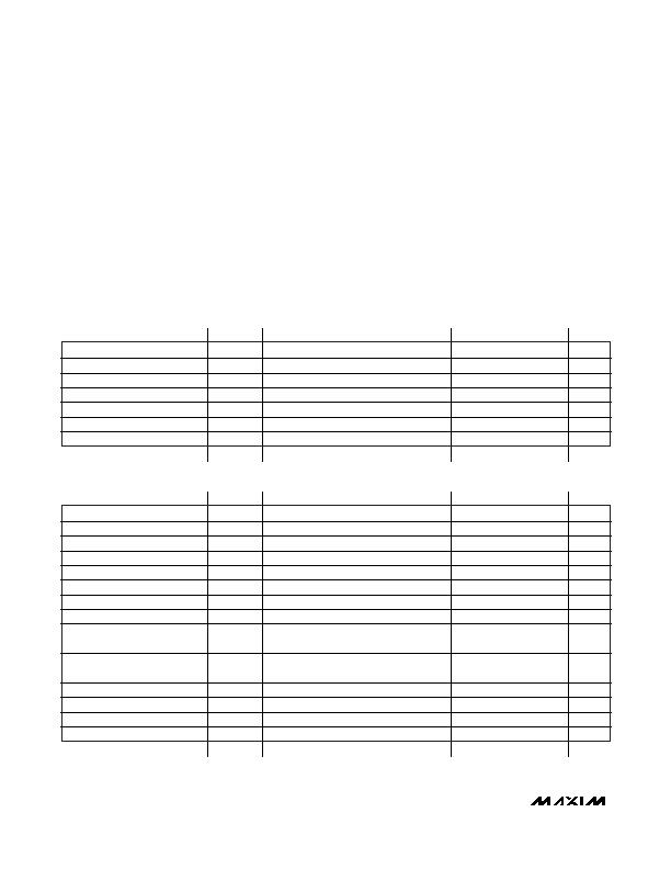
ABSOLUTE MAXIMUM RATINGS
RECOMMENDED OPERATING CONDITIONS
(T
J
= -40癈 to +135癈.)
Stresses beyond those listed under
Absolute Maximum Ratings
may cause permanent damage to the device. These are stress ratings only, and functional
operation of the device at these or any other conditions beyond those indicated in the operational sections of the specifications is not implied. Exposure to
absolute maximum rating conditions for extended periods may affect device reliability.
Voltage Range on V
CC
and LOAD Relative to GND
Continuous .........................................................-0.3V to +18V
1ms Maximum ....................................................-0.3V to +22V
Voltage Range on ILIM and VRAMP
Relative to GND.....................................-0.3V to (V
CC
+ 0.3V),
but not to exceed +18V
Voltage Range on TIMER Relative to GND ...........-0.3V to +5.0V
Drain Current
Continuous...........................................................................4A
Peak...................................................................................15A
Operating Junction Temperature Range...........-40癈 to +135癈
Storage Temperature Range.............................-55癈 to +135癈
Soldering Temperature...........................Refer to the IPC/JEDEC
J-STD-020 Specification.
PARAMETER
SYMBOL
CONDITIONS
MIN
TYP
MAX
UNITS
Supply Voltage
V
CC
(Notes 1, 2)
9.0
13.2
V
R
ILIM
Value
R
ILIM
20
400
C
VRAMP
Value
C
VRAMP
0.04
5.00
糉
C
TIMER
Value
C
TIMER
0.04
5.00
糉
TIMER Turn-On Voltage
V
ON
2.6
5
V
TIMER Turn-Off Voltage
V
OFF
-0.3
+2.0
V
ELECTRICAL CHARACTERISTICS
(V
CC
= +12V, T
J
= +25癈, unless otherwise noted.)
PARAMETER
SYMBOL
CONDITIONS
MIN
TYP
MAX
UNITS
Supply Current
I
CC
(Note 3)
1.1
2.00
mA
UVLO Rising
V
UVLOR
7.5
8.0
8.5
V
UVLO Falling
V
UVLOF
6.5
7.0
7.5
V
UVLO Hysteresis
V
UVLOH
1
V
On-Resistance
R
ON
25
32
m
MOSFET Output Capacitance
C
OUT
500
pF
LOAD Voltage During Off State
V
LOFF
(Note 4)
200
mV
Delay Time from Enable to
Beginning of Conduction
t
POND
C
VRAMP
= 1糉
5
ms
Gate-Charging Time from
Conduction to 90% of V
OUT
t
GCT
C
VRAMP
= 1糉, C
LOAD
= 1000糉
48
66
80
ms
Shutdown Junction Temperature
T
SHDN
(Note 5)
120
135
150
癈
Thermal Hysteresis
T
HYS
(Note 5)
40
癈
TIMER Charging Current
I
TIMER
70
80
92
糀
Overvoltage Clamp
V
OVC
13.5
15.0
16.5
V
发布紧急采购,3分钟左右您将得到回复。
相关PDF资料
DS600U+T&R
IC SENSOR TEMP 8-USOP
DS620U+
IC THERMOMETER/STAT DIG 8MSOP
DS7505U+T&R
IC DGTL THERMOMETER 2WIRE 8-USOP
DS75LVU+T&R
IC SENSOR TEMP DIGITAL 8MSOP
DS75LXS+
IC THERMOMETER/STAT DIG 8-SOIC
DS75U+T&R
IC THERMOMETER/STAT DIG 8-MSOP
FAN4010IL6X_F113
IC CURRENT SENSE 0.2% 6MLP
FAN5069EMTCX
IC REG DL BCK/LINEAR 16TSSOP
相关代理商/技术参数
DS4560S+
制造商:Maxim Integrated Products 功能描述:- Rail/Tube
DS4560S+T&R
制造商:Maxim Integrated Products 功能描述:- Tape and Reel
DS4560S-AR+
功能描述:热插拔功率分布 12V Hot-Plug Switch RoHS:否 制造商:Texas Instruments 产品:Controllers & Switches 电流限制: 电源电压-最大:7 V 电源电压-最小:- 0.3 V 工作温度范围: 功率耗散: 安装风格:SMD/SMT 封装 / 箱体:MSOP-8 封装:Tube
DS4560S-AR+T
功能描述:热插拔功率分布 12V Hot-Plug Switch RoHS:否 制造商:Texas Instruments 产品:Controllers & Switches 电流限制: 电源电压-最大:7 V 电源电压-最小:- 0.3 V 工作温度范围: 功率耗散: 安装风格:SMD/SMT 封装 / 箱体:MSOP-8 封装:Tube
DS4560S-LO+
功能描述:热插拔功率分布 12V Hot-Plug Switch RoHS:否 制造商:Texas Instruments 产品:Controllers & Switches 电流限制: 电源电压-最大:7 V 电源电压-最小:- 0.3 V 工作温度范围: 功率耗散: 安装风格:SMD/SMT 封装 / 箱体:MSOP-8 封装:Tube
DS4560S-LO+T
功能描述:热插拔功率分布 12V Hot-Plug Switch RoHS:否 制造商:Texas Instruments 产品:Controllers & Switches 电流限制: 电源电压-最大:7 V 电源电压-最小:- 0.3 V 工作温度范围: 功率耗散: 安装风格:SMD/SMT 封装 / 箱体:MSOP-8 封装:Tube
DS46
制造商:未知厂家 制造商全称:未知厂家 功能描述:Analog IC
DS4600
制造商:Promise Technologies 功能描述:QUAD INTERFACE 4-BAY HOT-SWAPPABLE DIRECT ATTACHED STORAGE W - Bulk